| Description and Name Prefix | Name | Status | Comment |
| Analysis name: Serdes_ | Alpha-numeric characters or underbar - case sensitive - start with alpha character |
2. Define Ch0 Transmitter Jitter
| Name | Description | Entry Value(s) | Status | Type | Limits | Comment | Action |
| TransmitterJitterType | Transmitter jitter type | Integer | [0, 1] |
0 = Use Ch0 IBIS-AMI jitter |
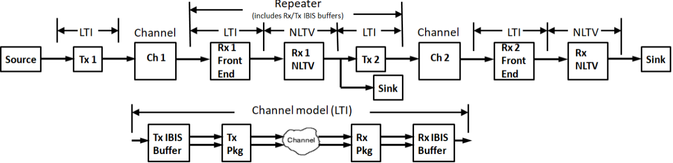
3. Define Channel 1 - the channel is linear and time invariant (LTI), but the AMI portion of IBIS-AMI models may be LTI or NLTV.
| Name | Description | Entry Value(s) | Status | Type | Limits | Comment | Action |
| ChSpec_1 | Channel 1 specification | Integer | [3] |
3 = Enable channel |
|||
| ReceiverRegenType | Receiver 1 output regenerator type | Integer | [0, 1] |
0 = None |
4. Define Channel 2 - the channel is linear and time invariant (LTI), but the AMI portion of IBIS-AMI models may be LTI or NLTV.
| Name | Description | Entry Value(s) | Status | Type | Limits | Comment | Action |
| ChSpec_2 | Channel 2 specification | Integer | [3] |
3 = Enable channel (Ch1) |
5. Define Ch2 Receiver Jitter
| Name | Description | Entry Value(s) | Status | Type | Limits | Comment | Action |
| ReceiverJitterType | Receiver Ch2 jitter type | Integer | [0, 1] |
0 = Use Ch1 IBIS-AMI jitter |
6. Setup Analysis - Bit-by-Bit Analysis is used by default; Statistical Analysis is used if system is LTI and SetupOption ForceBitByBitMode = 0.
| Name | Description | Entry Value(s) | Status | Type | Limits | Comment | Action |
| SymbolRate | Symbol rate (same as bit rate for NRZ) | Real | > 0 | Symbols per second (same as bits per second for NRZ) | |||
| SamplesPerSymbol | Samples per symbol (same as samples per bit for NRZ) | Integer | [4, 128] | ||||
| SetupOptionsRepeater | Setup analysis options | Integer | [1] |
0 = No |
7. Run Analysis
This tool is available for free to use on Windows with the Download button. Contact me if you would like it after the last availability date. This tool is an Add-On and requires the SerDesDesign.com Channel Simulator Download.| Select to run analysis | Waiting to run | ||
| Download Tool | Available until Oct. 2, 2025 |
8. Display Channel 1 Results
Go to the Eye Analysis Tool for detail eye analysis for this SerDes system (set ChAnalysisName = Serdes_'Analysis name')...| Display | Action | Action |
| Analysis log file | None | |
| 0. Channel spectrum magnitude | None | |
| 1. Channel spectrum phase | None | |
| 2. Channel data impulse response | None | |
| 3. Corrected channel impulse response | None | |
| 4. System worst/best case eye contours | None | |
| 5. System amplitude bathtub BER | None | |
| 6. System Rx input waveform | None | |
| 7. System Rx output waveform | None |
9. Display Channel 2 Results
| Display | Action | Action |
| 0. Channel spectrum magnitude | None | |
| 1. Channel spectrum phase | None | |
| 2. Channel data impulse response | None | |
| 3. Corrected channel impulse response | None | |
| 4. System worst/best case eye contours | None | |
| 5. System amplitude bathtub BER | None | |
| 6. System Rx input waveform | None | |
| 7. System Rx output waveform | None |