1. Define Analysis Name - Recall prior analysis. Note: Recall is under development and not available at this time.
| Description and Name Prefix | Name | Status | Comment | Action | Action |
| Analysis name: Redriver_ or Retimer_ | Alpha-numeric characters or underbar - case sensitive - start with alpha character |
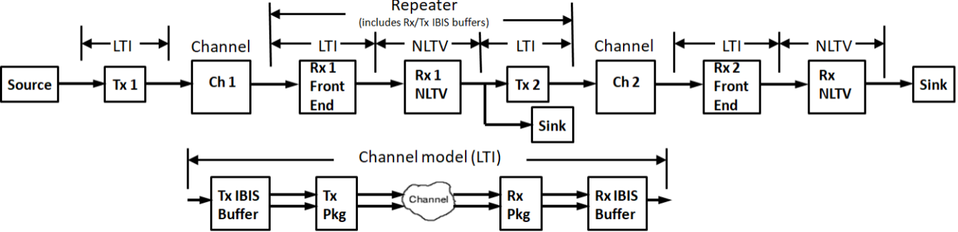
2. Define Transmitter - model is linear and time invariant (LTI).
| Name | Description | Entry Value(s) | Status | Type | Limits | Comment | Action |
| TransmitterType | Transmitter type | Integer | [0, 5] |
0 = None |
3. Define Channel - model is linear and time invariant (LTI).
| Name | Description | Entry Value(s) | Status | Type | Limits | Comment | Action |
| ChannelType | Channel specification type | Integer | [ 0, 3] |
0 = None |
4. Define Repeater Receiver LTI Front End - model is linear and time invariant (LTI).
| Name | Description | Entry Value(s) | Status | Type | Limits | Comment | Action |
| ReceiverFEType | Receiver front end type | Integer | [0, 4] |
0 = None |
5. Define Repeater Receiver NLTV model - model is nonlinear and time variant (NLTV); forces Bit-by-bit Analysis mode.
| Name | Description | Entry Value(s) | Status | Type | Limits | Comment | Action |
| ReceiverCDRDFEType | Receiver CDR/DFE type | Integer | [0, 6] |
0 = None |
6. Define Repeater Transmitter - model is linear and time invariant (LTI).
| Name | Description | Entry Value(s) | Status | Type | Limits | Comment | Action |
| TransmitterType2 | Transmitter type | Integer | [0, 5] |
0 = None |
7. Define 2nd Channel - model is linear and time invariant (LTI).
| Name | Description | Entry Value(s) | Status | Type | Limits | Comment | Action |
| ChannelType2 | Channel specification type | Integer | [ 0, 3] |
0 = None |
8. Define 2nd Channel Receiver Front End - model is linear and time invariant (LTI).
| Name | Description | Entry Value(s) | Status | Type | Limits | Comment | Action |
| ReceiverFEType2 | Receiver front end type | Integer | [0, 4] |
0 = None |
9. Define 2nd Channel Receiver CDR/DFE - model is nonlinear and time variant (NLTV); forces Bit-by-bit Analysis mode.
| Name | Description | Entry Value(s) | Status | Type | Limits | Comment | Action |
| ReceiverCDRDFEType2 | Receiver CDR/DFE type | Integer | [0, 6] |
0 = None |
10. Setup Analysis - With LTI system, analysis uses Statistical mode. With NLTV system, analysis uses Bit-by-bit mode.
| Name | Description | Entry Value(s) | Status | Type | Limits | Comment | Action |
| BitRate | Bit rate | Real | > 0 | Bits per second | |||
| SamplesPerBit | Samples per bit | Integer | [4, 128] | ||||
| SetupOptions | Setup analysis options | Integer | [0, 1] |
0 = No |
|||
| SetupBitByBitMode | Setup bit-by-bit mode | Integer | [0, 1]] |
0 = No |
|||
| RepeaterType | Repeater type | Integer | [0, 1] |
0 = Redriver |
|||
| GenerateModels | Generate IBIS-AMI repeater model after Run with satisfactory results | Integer | 0 or 4 |
0 = No |
Info... |
11. Run Analysis
| Select to run analysis | Waiting to run |
12. Display Results Log File
| Display | Action |
| Analysis log file |
13. Display Channel 1 Results
| Display | Action |
| 1.1. Channel and System LTI spectrum magnitude | |
| 1.2. Channel and System LTI spectrum phase | |
| 1.3. Channel data impulse response | |
| 1.4. System LTI impulse response | |
| 1.5. System worst/best case eye contours | |
| 1.6. System amplitude bathtub BER | |
| 1.7. System waveform |
14. Display Channel 2 Results
| Display | Action |
| 2.1. Channel and System LTI spectrum magnitude | |
| 2.2. Channel and System LTI spectrum phase | |
| 2.3. Channel data impulse response | |
| 2.4. System LTI impulse response | |
| 2.5. System worst/best case eye contours | |
| 2.6. System amplitude bathtub BER | |
| 2.7. System waveform |