A SerDes system for high speed digital data typically requires equalization to counter act the high loss in the channel that closes the data eye pattern at the receiver side. This equalization is often applied at the transmit and receive side of the channel.
One common equalizer approach used in receive circuits is a continuous time linear equalizer (CTLE).
Though the circuit implementation can be quite detailed, the algorithmic point-of-view defines a CTLE using s-domain poles and zeros.
The s-domain transfer function, H(s), for a CTLE with n zeros and m poles is defined as follows:
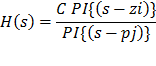
where s = j*w; C is a scaling factor; PI is the mathematical product operator; all poles and zeros are in radians/sec, i= 1,…,n; j=1,…,m.
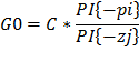
The gain at 0 Hz, G0, is:
For simulation, the Bilinear Transform is used to convert the S-domain transfer function H(s) to its Z-domain IIR transfer function H(z). Bilinear transformation will
result in a Z-domain transfer function that is not a linear mapping of the S-domain pole-zero system. Therefore, the specified poles and zeros are pre-warped before applying the Bilinear Transform. With pre-warping, the resulting digital filters will meet the desired specification at the critical frequencies. H(s) is defined in the frequency domain and its time domain impulse response is derived.
See CTLE detail (listed as Rx CTLE) in References > Equalization Introduction and RX FIR & CTLE Equalization
Follow the steps to define the CTLE, setup the CTLE analysis, run the analysis, and display the CTLE analysis results. Observe the CTLE frequency domain characteristic and its time domain impulse response.